
![]()


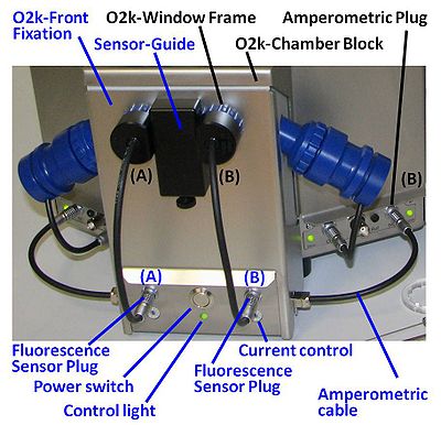
Fluorescence-Control Unit

| Description | Fluorescence-Control Unit with O2k-Front Fixation, Current-Control (O2k-Chamber A and B) for regulation of light intensity of the photodiodes in the fluorescence sensors. A component of the O2k-Fluorescence LED2-Module. |
|---|---|
| Product ID | 44100-01 |
| Type | O2k, MultiSensor, O2k-Fluorescence LED2-Module |
| Link | O2k-Fluorescence LED2-Module |
| Image | 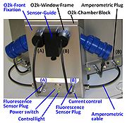 |
O2k-Guide
Setup of the O2k-Fluorescence LED2-Module
- Switch off the O2k with the power switch on the rear of the O2k-Main Unit.
- Remove both blue O2k-Window Frames. Insert the O2k-Window Tool around the outer rim of the window frame and unscrew counter clockwise.
- Remove the Sensor-Guide (‘nose’) from the O2k-Front Fixation of the Fluorescence-Control Unit. Loosen the small fixation screw and pull out the Sensor-Guide.
- Place the Fluorescence-Control Unit below the O2k-Chamber Block. Align the windows of the O2k-Front-Fixation with the windows of the O2k-Chamber Block, re-insert the O2k-Window Frames, and screw them finger-tight onto the O2k-Main Unit.
- Re-attach the Sensor-Guide to the O2k-Front-Fixation. Fasten the fixation screw finger-tight.
- Place the power-cables from the rear of the Fluorescence-Control Unit in the middle below the O2k-Main Unit from front to rear. Unplug the mains power cable of the O2k and plug it into the female plug of the Fluorescence-Control Unit. Insert the male plug of the Fluorescence-Control Unit into the mains socket at the rear of the O2k.
- Connect the amperometric cables attached to the side of the Fluorescence-Control Unit to the ‘Amp’ plugs (labelled "NO" in Series D-E) on the O2k-Main Unit.
In this configuration the O2k can be used for high-resolution respirometry and fluorometry. It is not necessary to dismount the Fluorescence-Control Unit for basic HRR when a fluorescence singal is not recorded.
O2k-Guide: Setup - next step - Mounting a Filter-Cap
Power on
- Switch on the power of the O2k-Main Unit (rear).
- Press the power switch on the front panel of the Fluorescence-Control Unit. Check that the central green control light is on.
Control of LED-intensity
The light intensity of the LEDs is set by the current control, independent for each fluorescence sensor (O2k-Chamber A and B). The current is controlled by a switch on the front panel of the Fluorescence-Control Unit and DatLab in a very wide range for optimization according to sample and fluorophore requirements. At higher LED-intensity the optical sensitivity is increased, i.e. the signal change per concentration change is enhanced. However, even moderately intensive light may exert negative effects: (i) Damage to the sample reducing the biological activity. (ii) Damage to fluorophores catalyzing degradation and various side reactions. Therefore, the LED-intensity should be kept as low as compatible with a smooth signal, i.e. when the resolution is just not limited by noise or disturbances. The values indicated in the table for application specific settings are only suggestions to start with. It is recommended to optimize the light intensity specifically for each application. There are two methods to set the LED intensity
A.) Setting the LED Intensity from DatLab (recommended)
- Bring the switch on the front panel of the Fluorescence- Control Unit into position 9 (use the small supplied srew driver)
- From the DatLab menu choose [Oxygraph]/[O2k-Control]
- Multiply the desired LED current in mA (e.g 2 mA) by 100 (e.g. 2 *100 = 200 mV)
- Enter the result in the field "Amp Polarisation Voltage [mV]" for the desired or both chambers
- Click "Send to Oxygraph" or "Connect to Oxygraph-2k" to apply the new settings
Limitations: For Series D oxygraphs the LED intensity has to be set to the same value for both chambers. The maximum LED intensity is 20 mA.
B.) Setting the LED intensity directly at the Fluorescence-Control Unit Use the small supplied screwdriver to bring the switch on the front panel of the Fluorescence- Control Unit to the desired position using the table below:
| Position | 0 | 1 | 2 | 3 | 4 | 5 | 6 | 7 | 8 | 9 |
|---|---|---|---|---|---|---|---|---|---|---|
| LED current [mA] | off | 0.02 | 0.5 | 1 | 2 | 5 | 10 | 20 | 30 | variable, see method A |
Amplification
The current from the photodiode is converted to a voltage and amplified by the gain setting in DatLab [Oxygraph]/[O2k-Control]. At a gain of 1, a current of 1 nA is recorded as a voltage of 1 mV (0.001 V). At gain 100, 1 nA corresponds to 100 mV (0.1 V). The amplified signal can be recorded in the range from -10 to +10 V.
1
|
0.001 | 1000
|
+-10000
|
333
|
10
|
0.01 | 100
|
+-1000
|
33
|
1000
|
1 | 1
|
+-10
|
0.3
|
The gain setting should be chosen so that the maximum observed voltage is well below 10 V. If in an initial experiment the maximum observed raw signal was e. g. 9 V the gain should be reduced for further experiments to avoid an "off scale" , i.e. 9.99 V signal. If, on the other hand, the maximum recorded raw signal was considerable lower than 1 V (e.g. 0.2 V) the gain can be increased to avoid being limited (in the resolution) by digital noise.
O2k-Guide: O2k-Fluorescence_LED2-Module#Calibration